When working with Geometry nodes, we have an increasing number of nodes to use that allow us to control all of the aspects of our models and how they are constructed. Some of these nodes are easy to understand, while other nodes, such as the Raycast node, require some more explanation in terms of how they work and what they are used for.
The Raycast node is used to project an attribute of one object, such as the geometry position or normal direction, in the form of a ray that is directed towards the main model to alter its shape based on ray direction, positioning, etc. An object info node is required to reference a secondary object that the rays are projected from.
While it is one of the more difficult nodes to learn and use, it does offer a more unorthodox style to modeling that can also be useful for animation, as it uses one object to control the geometry of another as a control point.
The Structure Of The Raycast Node
To access the raycast node, use the Shift + A hotkey to open up the add menu in the geometry nodes editor and then go to Geometry.
Within the geometry many you find Raycast, select this and position it within your node tree. The node itself should look like this.
As you can see its one of the larger nodes with a series of inputs and outputs.
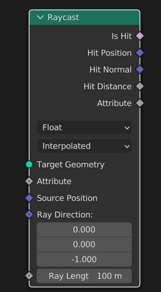
Target Geometry
The most important one to start with is the target geometry input. This is where we assign the secondary object that we want to use to cast the rays from.
We do not connect the geometry of the main object to this node socket. Instead, choose the object that wants to project the rays from and drag and drop from the outliner to create an object info node for that object.
This target geometry can exist either inside or outside the model, but the ray direction must create a straight line between the target geometry and the primary model.
We can use the target geometry to control our rays, and those rays can manipulate the geometry of the main model in various ways.
For example, we can use the Raycast modifier to delete a section of our model using Suzanne as the target geometry from the inside.
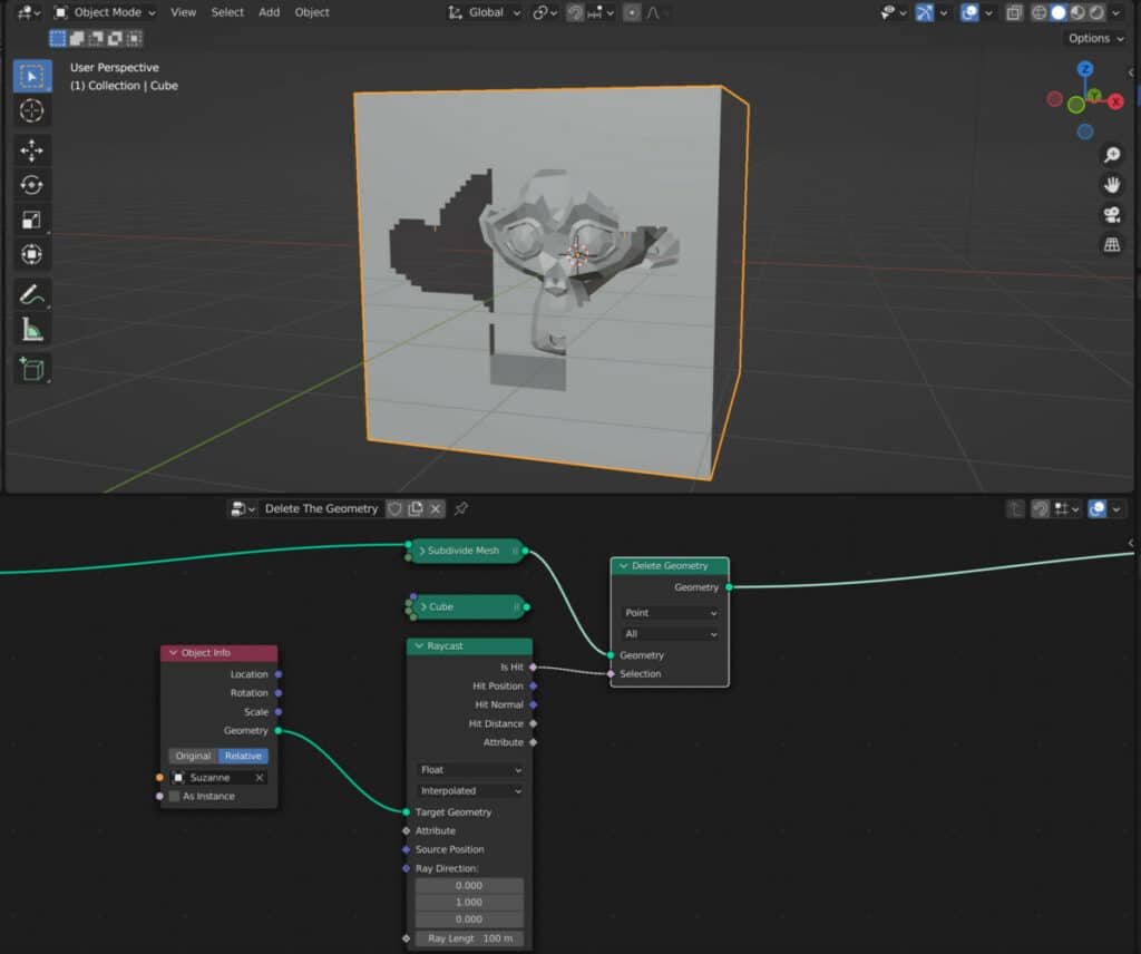
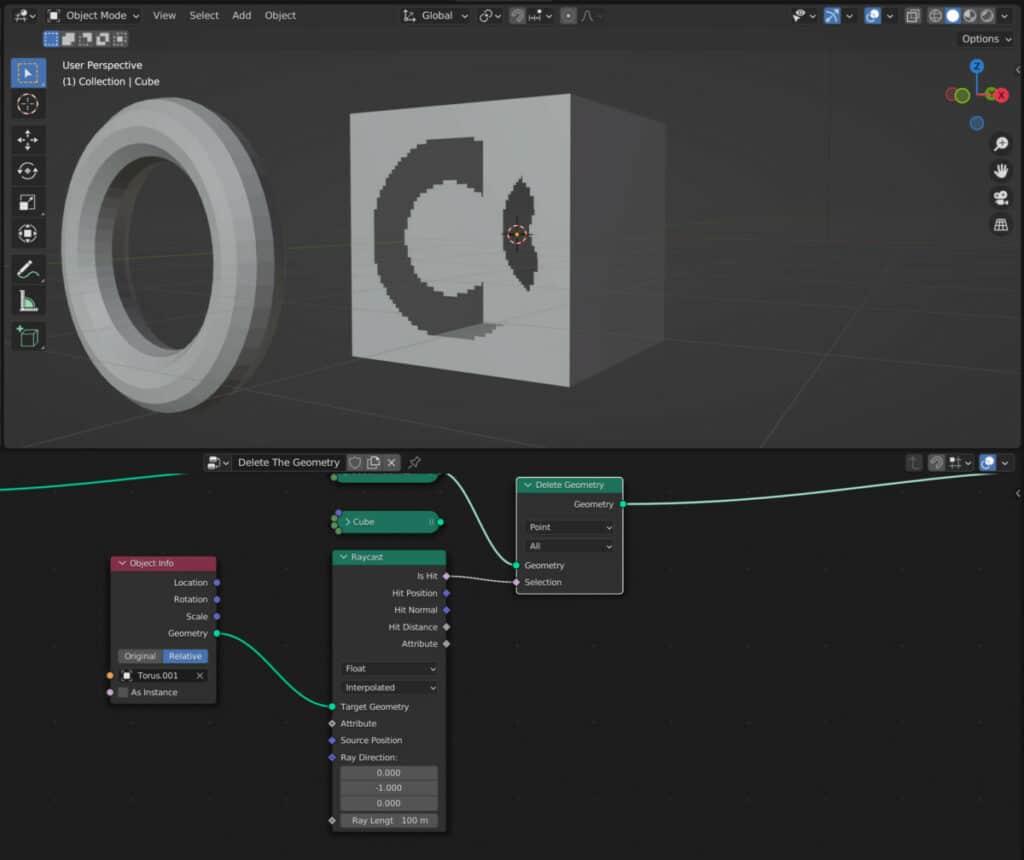
We can also use an object on the outside of our model to delete geometry, so long as the rays are pointed towards the target.
Attribute Input
The attribute input gives us more control by assigning an attribute that will be interpolated when rays from the target geometry are returned.
This attribute can be in the form of an existing attribute found in the spreadsheet or a custom one, like a texture.
The data that this input looks to receive changes based on the data type that has been selected. By default, this is set to a float value, so if you want to use a vector-based attribute, you will change the data type to vector.
This is the only input where the node socket changes based on the data type.
To output the data from any attribute, you must then use the attribute output to transfer.
Source Position
This represents the starting point of each casted ray. By default, this is where the vertices are located on the target geometry based on the position attribute.
Ray Direction
Another important parameter, the ray direction, is how the Raycast node projects the target geometry in the X, Y, and Z axis.
The rays must be directed towards the primary model; otherwise, the Raycast node will not work.
So if your target geometry is to the positive right of the main model, then you will need to set the X value of the ray direction to 1. If it is on the opposite side, which is the negative X direction, then you would set it to -1.
By using multiple axis, we can move the ray across the object in all directions allowing for more control.
For even more control, we can use an additional object, such as an empty, and with an object info node, use the location value of the empty to change the ray direction by plugging it into the input.
The rays can also be projected from multiple directions by using the Normals attribute. If projecting from inside an object, flip the normals first, add the normal node, and connect it with the ray direction.
The Ray Length
This input uses an integer value to determine the total length the rays will travel until they are no longer calculated.
Once it passes this threshold, the ray registers as no hit, similar to if the ray was pointing in a different direction.
The unit of measurement used for the ray length will change automatically when it is changed for Blender by going to the scene tab in the properties panel and changing the length unit.
The Data Type Node
This mode represents the type of data that Blender plans to use for the Raycast node. By default, it is set to the Float type but can be any of the following.
- Float: Single numerical value
- Integer: Single numerical whole number that cannot be a decimal
- Vector: Triple channel value that often represents the values of the X, Y, and Z axis
- Color: Triple vector channel that uses Red, Green, and Blue
- Boolean: True or False value
It is important to note that this mode selection is used for transferring attributes through the Raycast node. If you want to use a vector-based attribute, you will first change the data type to vector and then connect that attribute to the attribute input.
Connecting a node to the attribute input and changing the data type will disconnect the node.
The Mapping Mode
The second drop-down mode option is for the mapping. When the rays hit the main object, Blender receives information on how those rays hit the object.
With the mapping node, we control how the mapping is being calculated. More specifically, we are mapping the choosing attribute values to the model. There are two options or modes to choose from.
- Interpolated: In this mode, we use the face corners to map the geometry’s attributes. This is the smoother option and is best suited to most cases.
- Nearest: The rays are mapped to the nearest vertex that they hit. This method is slightly less accurate.
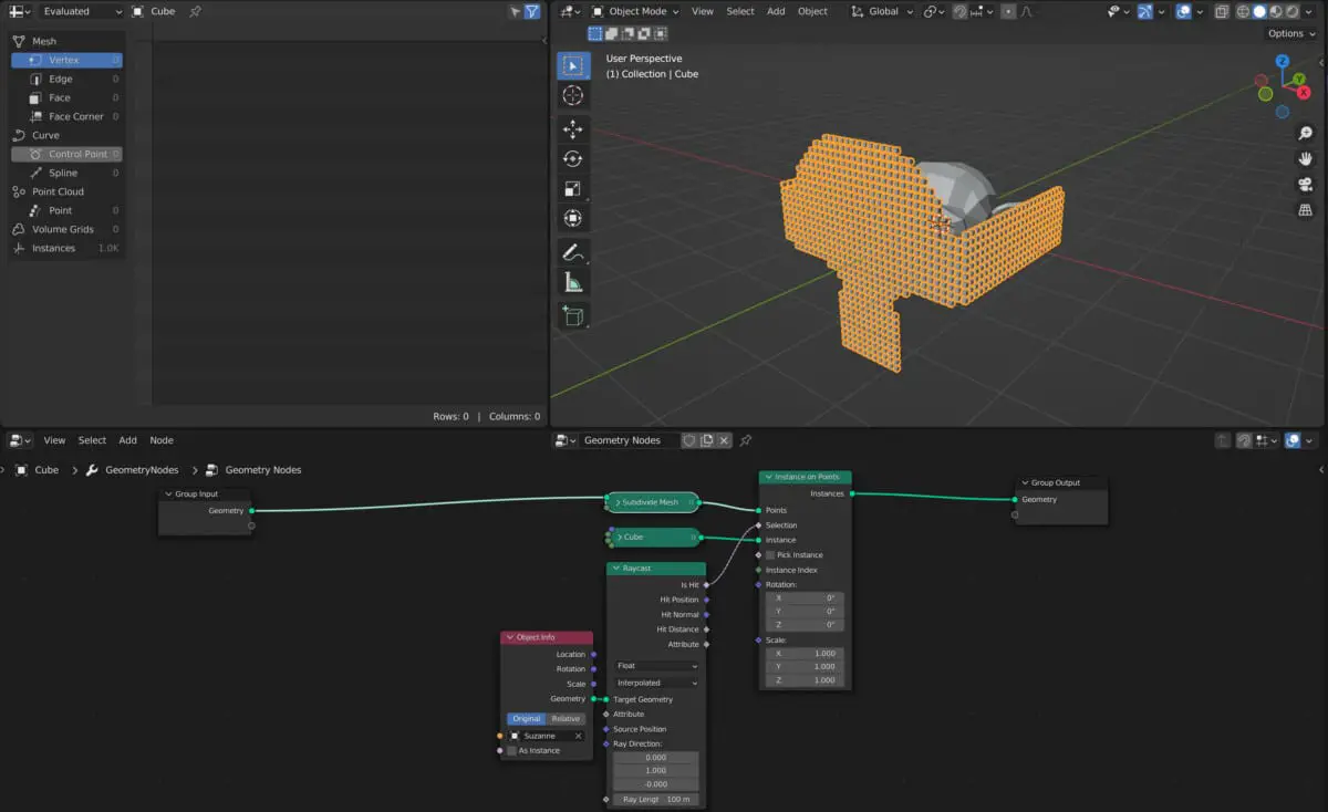
Is Hit Output
This standard output acts as a boolean to tell the next node to complete a specific action to all the points hit by the Raycast node.
This is best used when connected up to a selection input for something like the instance on points node to control where instances are created based on where the rays are cast.

In the example of this cube instancing effect, the ray direction is pointing out from Suzanne’s front, and so all points on the model that read True for the Is Hit output will each generate an instanced cube.
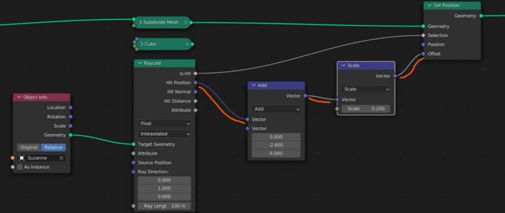
Hit Position
This output will transfer the position at which the ray connects with the targeted mesh. An example of this would be similar to how the shrinkwrap modifier works.
Suppose you connect the hit position output to the position input on the Set Position node. In that case, the models’ geometry will inherit the position attribute of the target geometry, which by default snaps the geometry to the target.
If you then use the hit position node to define the selection on the Set Position, you can use the ray direction to control where on the model the position attribute merges with the target.
Because the hit position is a vector value, it can be used to affect the vector values of other nodes, such as the offset value of the Set Position node or the rotate value of the Instance on Points node.
A vector math node can be connected in between to regain control of the vector and its three values, like when using a vector add node for the set position offset.
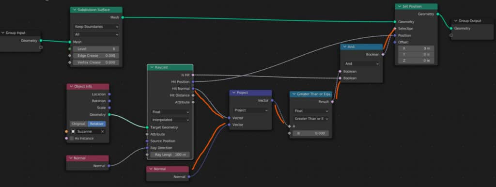
Hit Normal
This output uses the normal data recorded at the hit location, where the rays contact the target geometry. It uses the normal direction of the geometry instead of the position data to calculate.
One use case for the normal would be to create a node-based version of the shrinkwrap modifier. It can be used to wrap one object around another by combining with the hit position output using a boolean.
Hit Distance
This output calculates the distance the Raycast has traveled from the target geometry to the primary model.
This can be used for animation purposes or for when you want to delete geometry based on its proximity to the target.
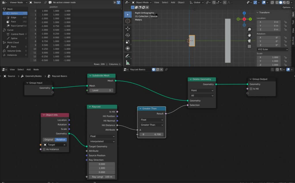
A good node to use for this output is a compare node. For example, if the distance between the target geometry and the model is above an assigned value, that geometry will be deleted.
Therefore the lower the value in the compare node, the less distance is required before the delete geometry takes effect.
Attribute
This socket is reserved for custom attributes that you connected to the Raycast node using the attribute input socket.
It requires you first to select the data type of the attribute you wish to use, such as a vector, and then connect that attribute to the Raycast node using the attribute input.
Thanks For Reading The Article
We appreciate you taking the time to read through the article, and we hope you found the information you were looking for. If you are interested in learning more about the different geometry nodes, check out some of the articles we have listed below.
- Beginners Guide To Using Geometry Nodes
- Edit Your Geometry Shape With Nodes
- What Are Fields In Geometry Nodes
- The Different Types Of Attributes In Geometry Nodes
- How To Control Vertex Groups In Geometry Nodes
BEGIN LEARNING AND DEVELOPING WITH OUR BLENDER VIDEO SCHOOL!!
Check out our course library if you are looking for a systematic and effective way to improve your skills as a 3D artist. Click Here To Learn Blender The Right Way!
